Application components, running as pods inside Kubernetes, can be distributed among multiple nodes of a cluster. Therefore the inter-node communication presents a particular challenge. Due to the heterogeneity of network environments found in the field, Kubernetes only defines the requirements, but does not implement them. Instead a common specification, the Container Network Interface (CNI) is used to connect to different suitable network implementations. Due to the decoupling and the universal acceptance of CNI a variety of compatible plugins is available to be used with Kubernetes.
This series sums up my bachelor’s thesis from September 2019, in which I covered the fundamentals of Kubernetes networking as well as the functional and technical differences of three popular networking plugins. Extending on this I extracted criteria to compare also other plugins and to be used as the basis for choosing a suitable plugin.
The first part of this series covers the fundamentals of container networking with Docker as reference. We will apply this knowledge to fully understand the internal networking mechanisms of Kubernetes and the “pod network“. The article will also answer the question why we need a Kubernetes network plugin in the first place. The second part will then dive into the particular implementations Project Calico, Cilium and Weave Net and will explain their fundamental paradigms and functional differences. At the end of the series you should then have an overview of the major concepts of Kubernetes networking and also know the criteria by which to choose the most suitable network plugin for your particular environment.
[Diesen Beitrag auf deutsch lesen.]
Fundamentals of Container Networking
Out of the box Docker containers operate in bridge-mode. The following graphic shows this classic scenario in which two Docker containers are started in a shared bridge network.
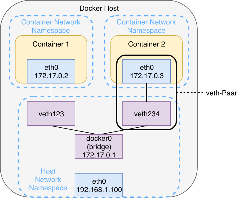
For each network Docker creates a virtual linux network bridge, initially named docker0. This bridge is then able to route traffic via the Linux Kernel routing table and out the existing physical interface of the host ( eth0). Internally it creates a separate address space in the form of a subnet. Each container is connected to the bridge via a veth-pair. This interface pair functions like a virtual point-to-point ethernet connection and connects the network namespaces of the containers with the network namespace of the host. The communication between containers of a docker bridge network always happens via the bridge – provided the IP address or the hostname of the other container is known. Since both containers have their own dedicated namespace, they each maintain their own routing table, interfaces and iptables rules.
If you start a Docker container with the option --net=container:<container-name>, with <container-name> being an existing container, the new container will be connected to the virtual interface of the existing container. Both containers now share the same namespace and therefore have a joint network stack. Communication is now possible using the loopback interface or localhost. Exactly this concept is also used by Kubernetes to allow communication between containers within a single pod. Remember: A pod can hold multiple containers (usually a main container and one or more sidecars). So a web server bound to port 8080 and running in container 1 is then reachable via http://localhost:8080 from container 2, even though there is no such process running there. In the context of Kubernetes this is called Container-to-Container communication. Graphic 2 visualizes this communication pattern.
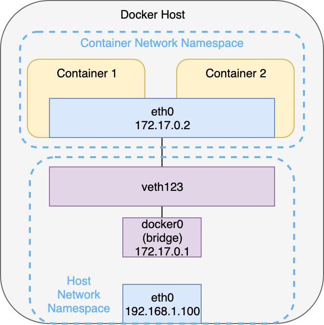
Within a Kubernetes Pod it’s worth to note that apart from the “user containers“ there is yet another so called “pause“ container. This container only exists to create and maintain the network namespace. If all the user containers fail or crash, the pod and its namespace remains to allow the other containers to join back after their restart.
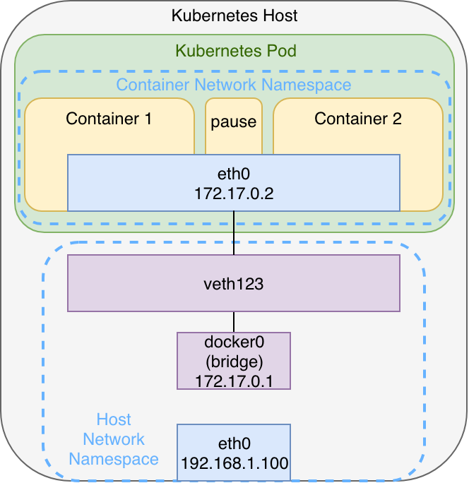
The architecture shown in graphic 3 can be observed when using i.e. minikube with Docker as container runtime. If there are more pods those will also be connected to the bridge via veth-pairs. This architecture might vary, depending on the container runtime and the particular network plugin used for multi-node clusters, as we will observe in the second part of the series. Understanding this architecture is still a good base to understand node-local networking mechanisms – especially when you have prior experience with Docker when starting with Kubernetes.
The Kubernetes Networking Model
After focusing on the networking between containers within a single pod, we shall now go one abstraction layer higher and look at communication between pods. To illustrate let’s imagine a simple web application, consisting of a frontend and a backend. Remember: Because both components have different characteristics (stateless vs. stateful), one would put them into individual pods, at least to scale them independently. To allow the web application to function properly, the pods need to be able to communicate with each other at all times – independently from the node which they currently run on. Regarding the Pod-to-Pod communication it’s important to ensure that pods on a single node as well as pods on a topological remote can establish communication at all times. After all Kubernetes’ job is to spread workload evenly among the available nodes, while abstracting away the actual hardware resources. It shall not concern the developer of an application if the frontend or backend pod run on the same or different nodes. The pod-to-pod communication is implemented like this:
Each pod receives a unique IP address, valid anywhere in the cluster. Kubernetes requires this address to not be subject to network address translation (NAT). This is intended to simplify the communication among application components by making each pod reachable via this IP address which is the same that is also bound to its virtual network interface.
For communication between pods on the same node this is implicitly achieved via the virtual bridge (L2) – see the explanation around graphic 3 above – archiving seamless cross nodes is more complex: First of all there needs to be some sort of IP address management (IPAM), in order for IP addresses not to be used multiple times or conflict in other ways. Furthermore the local bridge networks of all nodes need to be connected so communication can happen across nodes.
There are multiple approaches to implement such requirements: Quite simply they could be set up manually by an administrator or be managed by an external component – the network plugin – which is connected to the Kubelet. The Kubelet always serves as the primary interface between the Kubernetes API and the local container runtime. It’s running as an agent on every node. From a networking perspective the cross-node communication can be implemented on layer 2 (Switching) or layer 3 (Routing) or also as an overlay network.
A possible implementation of such a pod network could look like this:
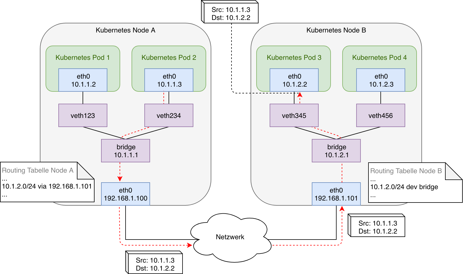
In this case the bridges on each node are connected and some simple routing rules are applied: Each node’s routing table holds routes to all the other nodes internal networks with the next-hop being the physical interface of the particular target node. Additionally there is another route for the node’s own subnet and local bridge network to allow incoming traffic from external as well as locally originating (i.e. a pod running in host mode) to be forwarded to the bridge.
The graphic illustrates a packet being initiated by pod 2 and the transmission of that packet across the physical connection between node A and node B to finally reach pod 3. The virtual ethernet pair ( veth-pair) serves as a logical connection between the network namespace of the pod and the network namespace of the host system. In case of a switched layer 2 network both nodes can communicate via ARP and their own MAC address directly. In case there was a router between node A and node B (layer 3) the subnet used on the bridge networks on each node would need to be added to its routing table as well.
In a nutshell the pod network illustrated in graphic 4 implements all the requirements defined by Kubernetes: Pods can communicate with all other pods, local as well as remote, and do so without any NAT. Also all nodes (or rather processes running there) can also reach all local and remote pods as well as all other nodes directly and without NAT. But as soon as packets targeting another pod reach a router on a public network the traffic will be dropped due to it being addressed to a private network. This results in the shown setup only being applicable if all nodes are connected to each other via a switch or if intermediate routers can be configured explicitly. Otherwise NAT would have to be used to mask the private addresses and in order to allow traffic to be routed. This is where tunnelling protocols or so called overlay networks come into play, which can be added via network plugins to a Kubernetes cluster. Even in local networks, in which tunneling protocols are not actually required, the manual tasks of configuring multiple nodes, as shown in graphic 4 is not manageable. This job is taken over and automated by network plugins.
The Container Network Interface (CNI)
The container network interface was developed by CoreOS (now part of RedHat) and in relation to the rkt container runtime. The goal was to define a common interface between network plugins and container runtime or orchestrator. Meanwhile CNI is common among container orchestrators – with the exception of Docker Swarm (which uses the Docker-specific solution libnetwork) – which results in a number of compatible plugins from 3rd parties.
CNI consists of a specification and some libraries to allow the development of plugins which configure network interfaces in Linux Containers. Furthermore the CNI project comes with a few „Core“ Plugins which cover fundamental functionality – i.e. creation of Linux bridges or connecting host and container to it. CNI only handles network connectivity of container and the cleanup of allocated resources (i.e. IP addresses) after containers have been deleted (garbage collection) and therefore is lightweight and quite easy to implement. Apart from Kubernetes CNI is also used for OpenShift, Cloud Foundry, Apache Mesos or Amazon ECS.
To better understand CNI it is worth looking into certains aspects of the specification: According to this a CNI plugin has to be provided as executable file (binary), which can be invoked by the container management system (in case of Kubernetes with Docker this would be the Kubelet) after a network namespace has been created to host a new container ( ADD operation). Following this step the plugin has to add a network interface inside the container namespace (following the example from graphic 4, this is the container-facing end of the veth-pair) and also ensure connectivity on the host (in our example this is the host-facing end of the veth-pair and the connection to the bridge). Finally it needs to assign an IP address to the created interface and add required routes maintaining consistency with the IP address management (IPAM) which is handled by an IPAM plugin. According to the specification the following operations have to be implemented:
- ADD (Adding a container to a network),
- DEL (Remove container from a network),
- CHECK (Validating connectivity) and
- VERSION (Respond with the CNI versions the plugin supports)
The configuration of a plugin has to happen via a JSON file. Further details can be found in the specification
Practically speaking a CNI conformant plugin could be realized via a BASH script, which implements the four operations in the form of individual, parameterized functions. The script would utilize existing tools like $ ip link oder $ ip route add to create and configure interfaces or add routes.
We have looked at the specification and have a first idea on how a plugin is to be implemented. But how is CNI utilized by Kubernetes? To Kubernetes using Docker as the Container Runtime (Dockershim) CNI is a network plugin itself. It is connected to the Kubelet running on each node, which is responsible for creating and deleting containers. A network plugins is selected via the option --network-plugin=<cni|kubenet>. This step is usually handled by installers like kubeadm. kubenet is the built-in “basic“ network plugin Kubernetes comes with. It also uses the CNI core plugins, but is not widely used. If an alternative container runtime like containerd or CRI-O is used via the Container Runtime Interface (CRI) the runtime will directly interact with the CNI plugin with no additional calls via the Kubelet or Dockershim.
In the case of Docker as container runtime a network plugin has to implement the NetworkPlugin interface (see GitHub). This specifies functions like SetupPod() and TearDownPod(). The Kubelet calls the first function after a pause container and therefore a new pod has been stated. The other function is called after a pause container and therefore a previously existing pod has been deleted. The CNI implementation inside the Dockershim uses the official CNI library provided for integrations (see GitHub). Roughly sketched the method calls after creating a new pod look like this:
- The Kubelet calls SetupPod(), which then calls addToNetwork() (see GitHub)
- addToNetwork() then uses addNetworkList() from the imported CNI library. This then invokes addNetwork() (see GitHub)
- Finally the ADD operation of the provided CNI-compatible plugin is invoked during addNetwork() (see GitHub)
To sum up, CNI is, by implementing the NetworkPlugin interface, a Kubelet network plugin itself. But it is also a specification for 3rd party network plugins such as Weave Net, by describing the expected operations and behavior.
Installing Kubernetes Network Plugins
Before we dive into the particular network plugins we need to understand how they are installed. Usually the project provides a YAML manifest containing all required Kubernetes resources. This only has to be applied to a cluster via $ kubectl create -f. This is due to the fact that there are usually more components required than just the single CNI binary implementing the functions to add or delete pods. Usually those components come in the form of one or more privileged pods, running as DeamonSet on each node. They influence the network configuration of the node or can even intercept and forward traffic independently to ensure communication across multiple nodes. Since having the CNI binary provide IP addresses to pods and connecting them to the host network namespace is not enough to provide the host with the required details on how to reach other Kubernetes nodes or pods – remember graphic 4 in which this information in the form of routes was provided manually. Additionally it’s possible to create and use overlay networks by having each node-local component communicate via a control-plane and implement mechanisms to encapsulate and decapsulate data packets.
Also to provide network policies additional components are required – potentially in the form of a privileged pod which monitors NetworkPolicy resources and applying iptables rules on the host. As you can see a NetworkPlugin consists of much more than just the CNI binary. But it’s also shown that components are interchangeable and the complexity of the networking lies within each implementation. They just have to be run on the target platform and then form a cluster-wide network – independently from any workload. The CNI plugin then simply provides the interfaces required to add and remove workloads to this network. Instead of privileged pods there also could be a routing daemon like BIRD running locally on the host to ensure connectivity between the different nodes. This makes you realize the loose coupling between the networking components and the general platform.
Summary
What to take away from this? The node-local networking mechanisms of Kubernetes are quite easy to understand when looking at Docker and they are realized using the Linux built-in tools. More complex then is the Pod-to-Pod communication across nodes. First the distribution of IP addresses without conflicts has to be ensured, so each pod is assigned its own, unique address. Additionally each pod has to be reachable cluster-wide and without any NAT. Realizing this might seem straightforward for a few nodes – looking at the setup on graphic 4 again – but is not practical for larger environments, potentially involving public networks, anymore. This is where network plugins come into play. They take on the job of all network configuration for pods – assigning IP addresses and connectivity to the established pod network – with no manual intervention required. With the de-facto standard CNI, serving as an adapter between Kubelet / container runtime and 3rd-party network plugins, a variety of solutions are available. Each using their own implementation and methods, but following the Kubernetes requirements to create a flat network for all nodes.
Three of those solutions, namely Project Calico, Cilium und Weave Net, we shall be looking at in great detail in part two of this series.
